The LaFayette radio station
By Daniel Maignan/F6HMT
(English translation by Neil Paterson/GM8IID)
The Bordeaux-Lafayette transmitting station, inaugurated in 1920, was located at Croix d'Hins, a village near Marcheprime, in the Gironde, 30km from Bordeaux. We went to the old site to look for the last remnants still in existence. This was an opportunity to retrace its history and to describe the installations at this mythical wireless telegraphy station that was the most powerful in the world at the time.
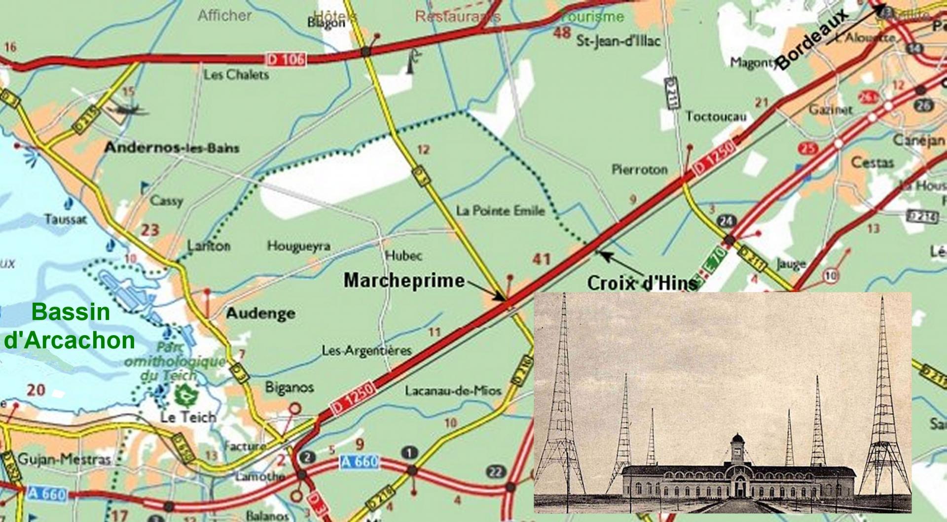
figure 1 - Croix d'Hins location map and site photo
1) Searching for the lost bases:
After having walked along some recently cleared ground, bordered by a small river, we passed through brush and copses mixed with brambles and bushes that scratched and whipped at our legs. Several pheasants took flight as we approached. A fine rain had started to fall, but the temperature was pleasant. After fifteen minutes of hard going, a pylon base appeared above the thickets. Once there we took several pictures, a bit tricky due to the surrounding vegetation. Only two of the original twenty-four concrete bases remain today and are very likely the sole remnants of the aerial system (figures 2 & 3).
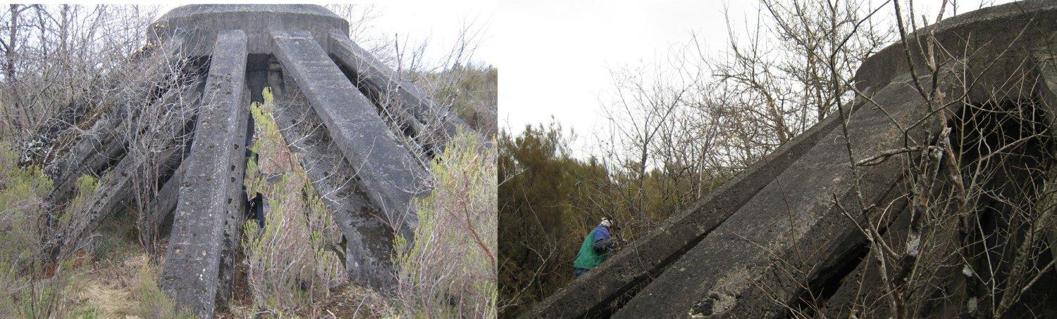
figure 2 figure 3
Climbing to the top looked hazardous because the concrete was covered by slippery moss. Our guide assured us that the second base, which we would now try to find, had steps. Indeed, after walking another sixty metres we spotted it. This site was clearer and better for photos but the steps were blocked by large branches. However, I managed to haul myself to the top. This base was much more interesting since the scrap men had left the whole metal socket, with the foot joint and pedestal mounting with its huge fixing bolt (figures 4 & 5).
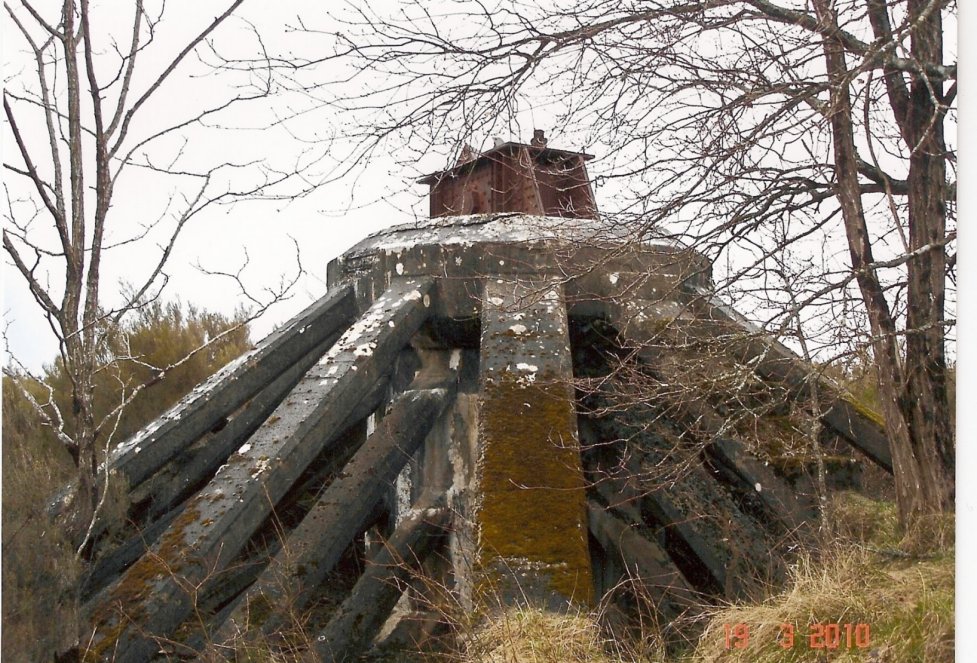
figure 4
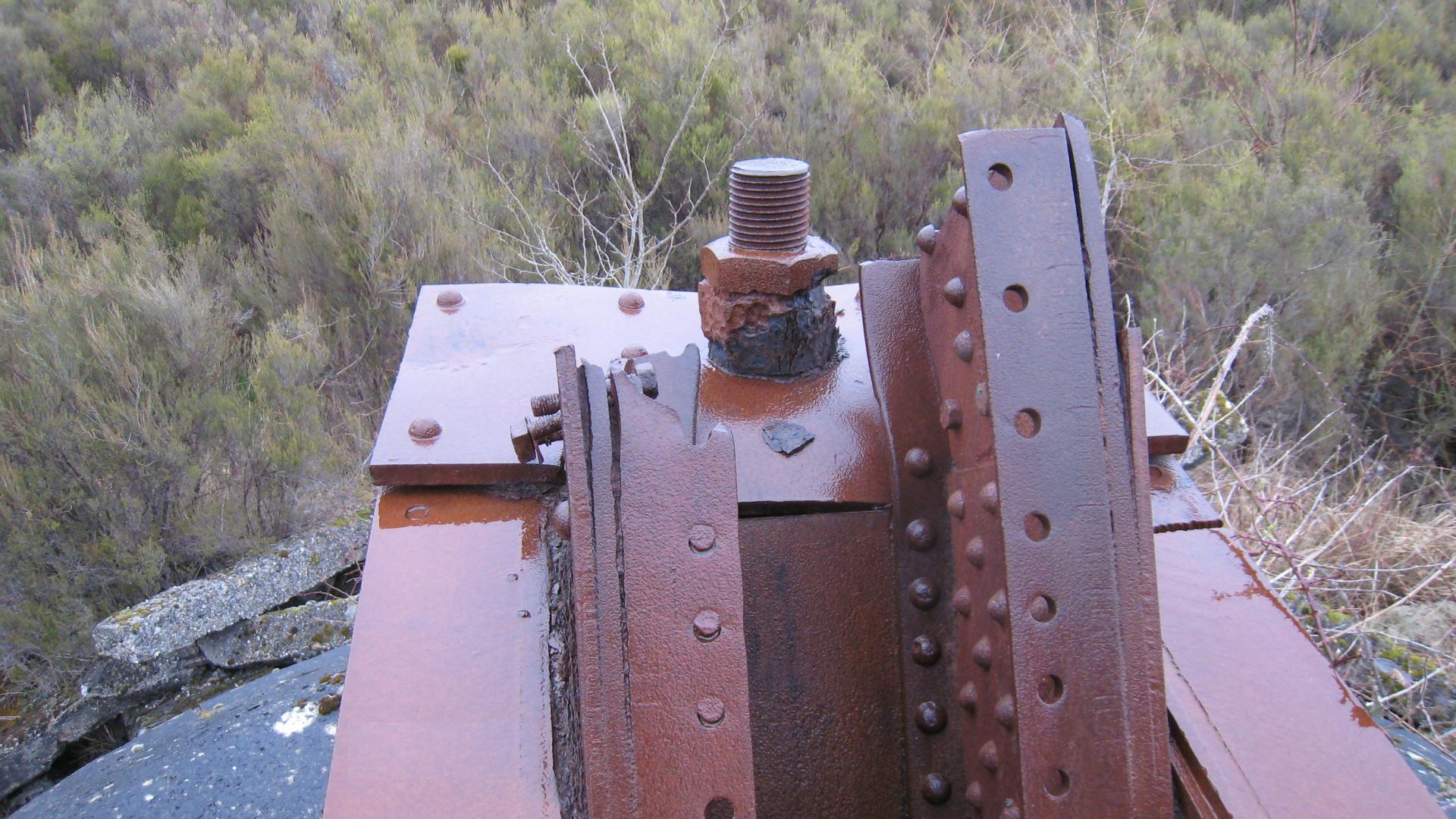
figure 5
The mat aerial was supported by two parallel rows of 4 pylons spaced 400m apart, giving a total length of 1200m. These 250m-high tripod pylons, each weighing 560 tonnes, rested on three bases 66m apart. Each base was 13m in circumference and 3.5m high. At the entrance to the site, where streets with evocative names (rue La Fayette, rue de la Maison Blanche, rue de la Station) intersect, four buildings in the style of the time, where the station staff lived, have now been renovated and transformed into stables.
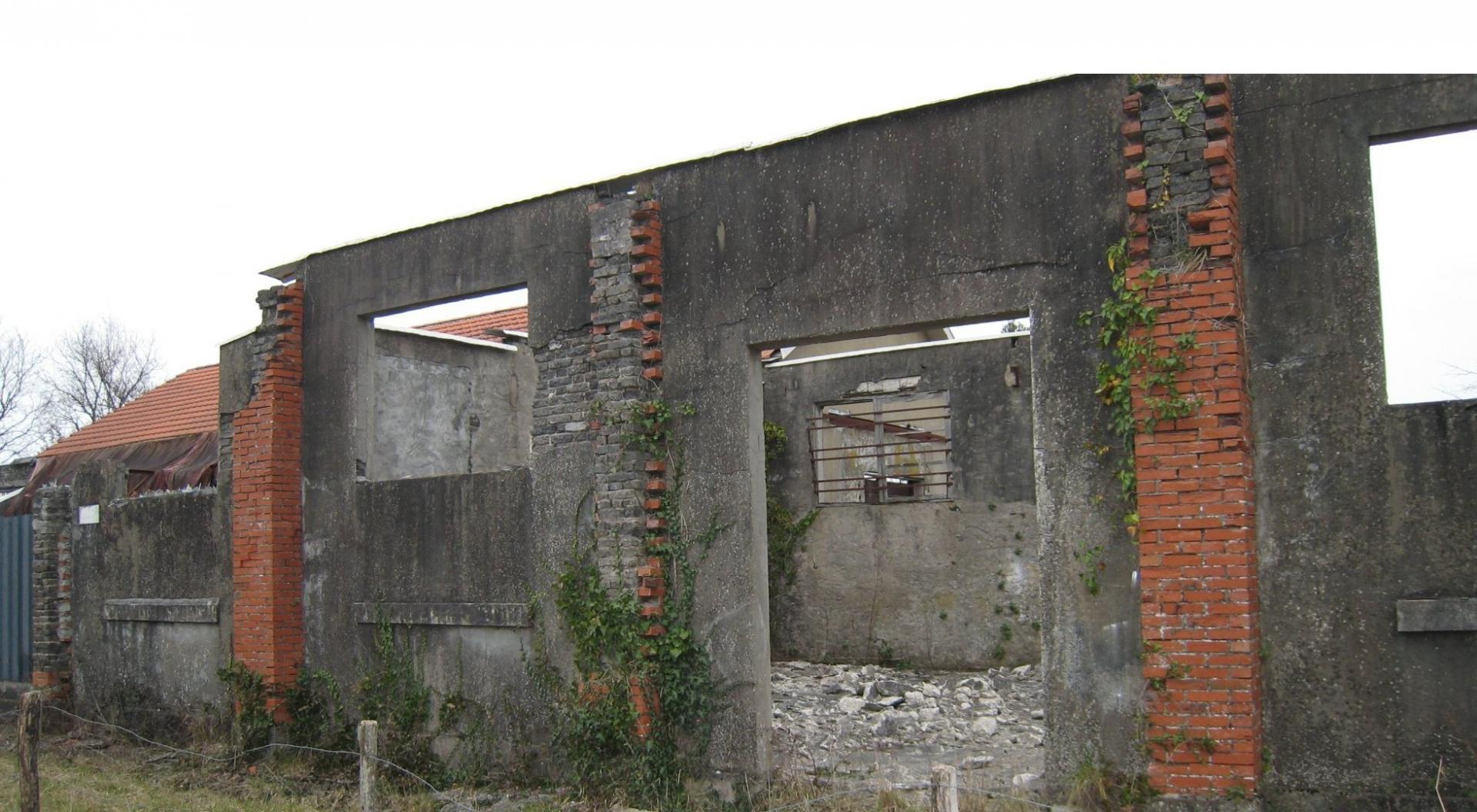
figure 6
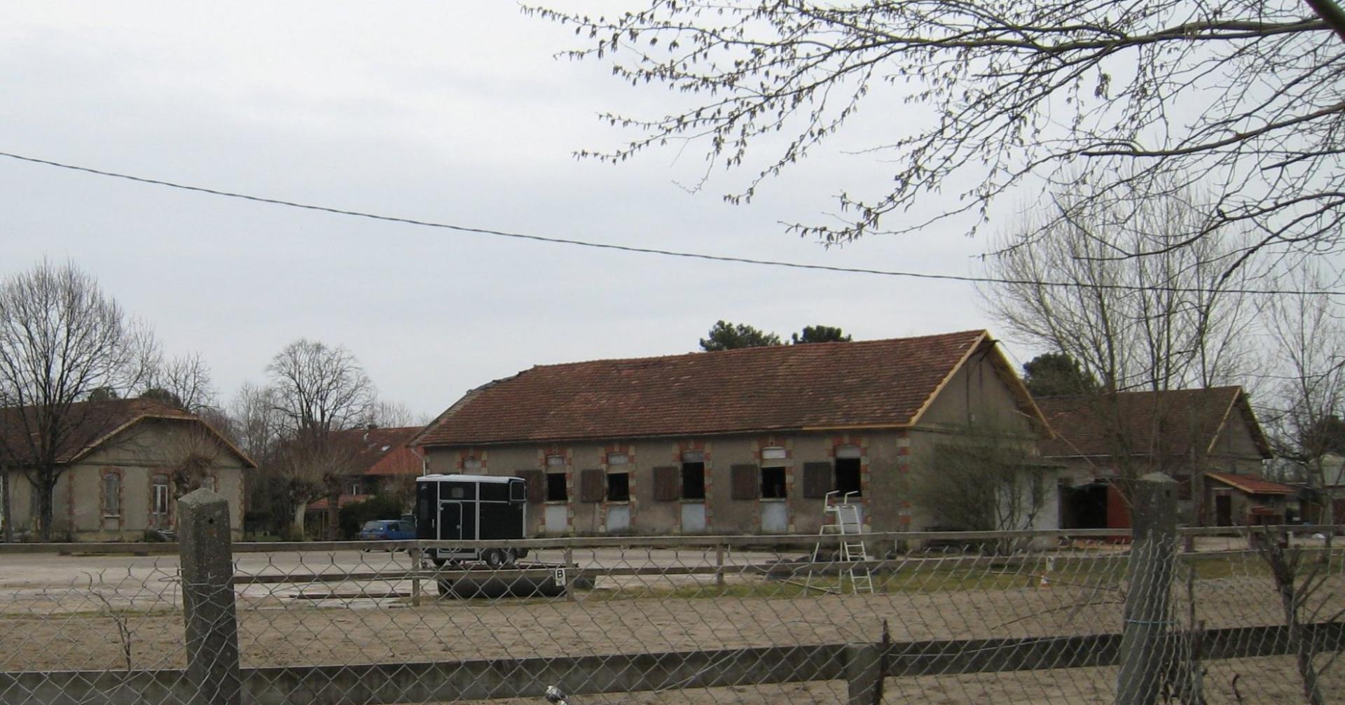
figure 7- Buildings today transformed into stables
There also remains a building which was used at some time as a garage for firefighting vehicles. The buildings which housed the workshops and the refectory are in ruins (figures 6 & 7). A few stones indicate where the cooling water basins had been. It is likely that tens of tons of copper wire from the ground/ earth plane are still buried.
2) History of the site:
Croix d'Hins is located on the Bordeaux<-> La Teste de Buch railway line, built around 1850 by the ‘Compagnie des Chemins de Fer du Midi’. The aviation company of Louis Blériot and the Voisin brothers had a test site built there around 1903. In 1909 it was decided to build a proper airfield, which was completed at the end of the same year. In 1910 various aeronautic events were staged, including ‘la grande semaine d’aviation’. Leon Delagrange, a famous aviation pioneer, died on January 4th during an inaugural flight. In 1913, on the eve of the First World War, the State, represented by the ‘Service du Genie du Departement de la Guerre’, acquired the land. As early as 1915, a gunpowder and grenade factory had been set up nearby, opposite the main road. This factory, staffed mainly by French and Spanish women (1,200 women, 600 civilian and enlisted men), suffered a violent explosion on April 21, 1916, with 42 victims. However the activity continued until the end of 1917.
3) The Lafayette transmitting station:
America entered the war in 1917. Through the sustained action of enemy submarines, the transatlantic cables were being regularly severed. In order to establish reliable links between the two continents, the use of emerging wireless telegraphy (TSF) technology was explored. At the time only two transmitting stations were capable of providing such links, the Eiffel Tower station (100kW) and the Lyon La Doua station (125kW). But the Eiffel Tower was under threat of aerial bombardment and La Doua was unable to guarantee a reliable link due to its geographical location. At the initiative of General PERSHING (figure 8), commander of the American Expeditionary Forces, the possibility of a new radio telegraphy station was explored.
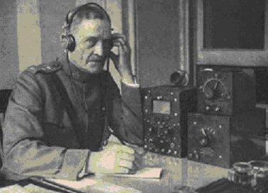
figure 8 - General Pershing
On October 4, 1917, an agreement ratifying construction of a new station was signed by France and the United States. France had proposed to use the huge, somewhat abandoned, 480ha site at Croix d'Hins. This was accepted by the Inter-Allied Commission because the location had many geographical advantages: it was at an elevated point in the region (59m altitude), only 30km from the port of Bordeaux (but still outwith any urban area) and, from a strategic point of view, far from the combat zones. In addition, it could easily be connected to the nearby rail network, and also benefit from power supplied by the hydroelectric dams of the Dordogne (in particular the Tuilières dam upstream of Bergerac). A decree of March 20, 1918 declared the acquisition of the land of the former airfield of Croix d'Hins for public use.
The station would be named ‘Lafayette’ in homage to the Marquis "hero of the two worlds" who had participated in the American War of Independence (1775-1783).
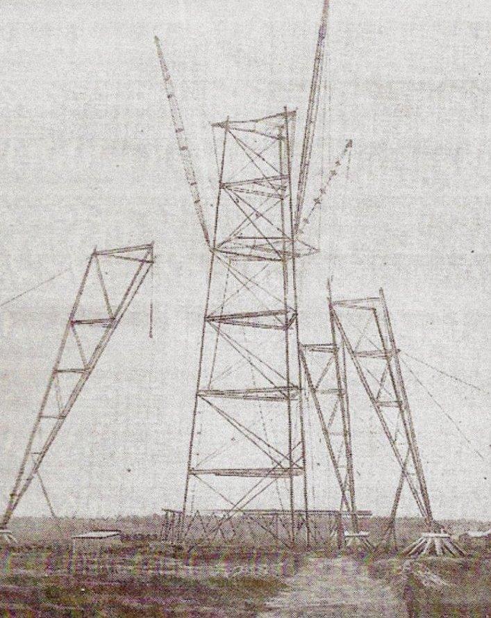
figure 9 - Pylon mounting, bases can be seen.
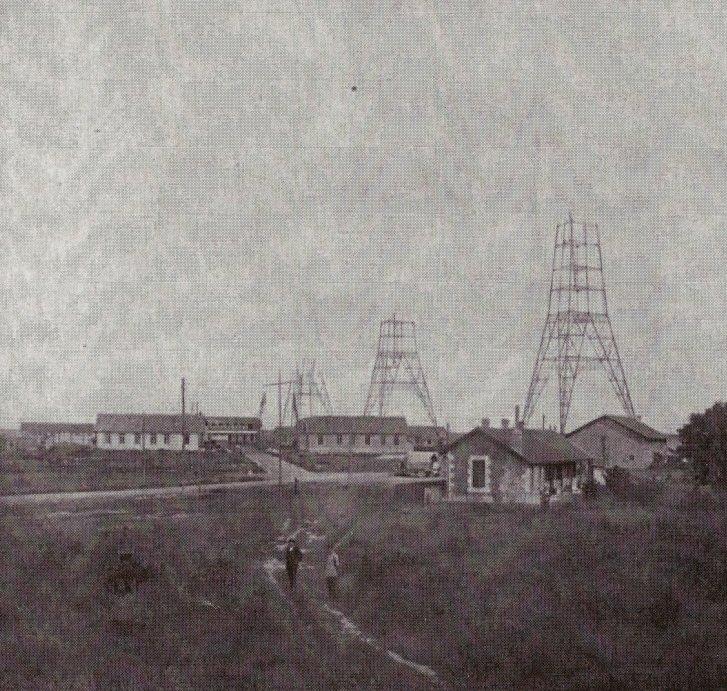
figure 10 - Construction of three pylons in progress
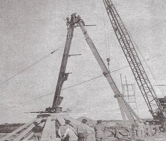
figure 11 - Pylon base mounting
Overall planning fell to Colonel Ferrié, on behalf of the French Armed Forces. His organisation was tasked with defining the technical project. Construction of the foundations for the pylons, as well as the construction of the buildings and electricity power line was entrusted to his military engineers. The US Navy was to be responsible for supplying the transmitters and pylons. In early 1918, a team of 750 Americans marines was sent to participate in the construction and installation of the infrastructure under the direction of Colonel Ferrié, with work beginning on March 7, 1918. Technical buildings, a water tower, a pond, a workshop, a refectory, staff accommodation and even a school were built. Erecting the pylons was particularly dangerous, with several fatal accidents (figure 9, 10 & 11). A link was made to the main line at the Croix d'Hins railway station in order to bring in the heavy parts, having been shipped from Pittsburg and landed at the port of Bordeaux. The rail line passed between the pylons and extended right in to the main building. But at the end of the war the American government recalled some of its men, resulting in a slowdown in work. At the armistice on November 11, 1918 work was halted, with only 6 of the 8 pylons near completion. However, allocation of the future station to civil commercial links was envisaged and work resumed in June 1919 after a new Franco-American agreement was signed in February 1919. In April 1920 the last pylons were erected, the general installation completed and reception tests carried out.
The first message was sent (in English) on August 21, 1920 as follows:
"Secretary of the Navy, Washington
This is the first wireless message to be heard around the world and marks milestone of the road of scientific achievement.
La Fayette radio station."
The official inauguration took place on December 18, 1920, with several French and American dignitaries taking part in the event: of note, General Ferrié, Admiral Magruder and Monsieur Deschamps (undersecretary of state for the PTT) attended (figure 12).
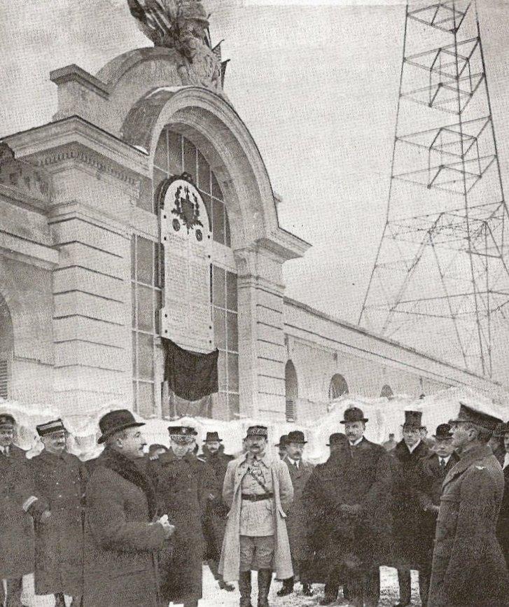
figure 12 - The official inauguration on December 18, 1920
From then on the staff was split into four teams of fifteen, including engineers, mechanics and telegraph operators, to ensure 24hr/ 24hr service. The 1MW arc delivered 500kW to the aerial, on seven possible wavelengths ranging from 19.15 km to 23.45 km. In 1922, the site was assigned by official decree from the Minister of War to the Under-secretary of State of the PTT (Post Office). The station provided links with ships and an international telegraph network with the French colonies (Tananarive, Djibouti, Brazzaville, Dakar, Conakry, Fort de France, Cayenne, Saigon, ..) which had previously been provided by cable. It also provided a link with the USA in addition to sending regular time and scientific signals on 23450meters, seismological telegrams, and press releases for embassies and news agencies. However links with South America and the Far East were quite erratic and strongly subject to propagation conditions.
In 1923, the arc transmitter was replaced by 500kW Bethenod-Latour high-frequency alternators made by SFR (similar to those used at the Sainte-Assise station in Seine et Marne). The station could now move from the telegraphy era into the telephony era and prepared itself for the new broadcast programmes. The arc transmitter remained as a backup. After 1923 only the 19150m wavelength (15666 kHz) was used. In 1924, the station was renamed ‘Bordeaux-Lafayette-PTT’. As at the Eiffel Tower, la Doua and Saint Pierre des Corps stations, the transmitter was controlled from the PTT’s central radiotelegraphy office on rue Froidevaux in Paris. The listening centre was directly linked to this office and was located in Villejuif.
Around 1928 the station, operated by the PTT, broadcast a daily programme of news and music that swamped all other broadcasts in the south-west of France, causing some discontent among listeners. In 1938/39, thermionic valve (vacuum tube) transmitters were installed.
From June 1940, the station was controlled by the Germans. The Kriegsmarine used the ultra long wave transmitter for communication with submerged U-boats. The station operated until the arrival of the allied forces and on August 22, 1944, the enemy destroyed the installations (including the main building, pumps and alternators) with explosives.
Three of the four pylons that had been spared were dismantled after the war, the last being used by firefighters for forest fire surveillance. This one hindered the approach to the airfield of Mérignac and was destroyed in 1953. The last 100kW transmitter was reassembled at the Sainte Assise station in 1946. In 1949, the French Navy considered a new long wave transmitter project for submarine communications but this was abandoned after the terrible forest fires during the summer. At the end of the 1960’s the land and buildings were transferred to the municipalities of Marcheprime and Mios. The gate to the site remained up until 1975, surmounted by a beautiful TSF logo which has unfortunately since disappeared.
It should be noted that it was on the Bordeaux-Lafayette transmitter that Marechal Pétain broadcast his speech of June 17, 1940, from the studios of Bordeaux.
4) Technical description of the original installations:
Figure 13 shows the huge installation, with the principal building and six of the eight 250m pylons, spaced 400m apart. The constituent parts of these tripod pylons (manufactured in the USA by Pitt-Des Moines Co steel mills in Pittsburgh, Pennsylvania) were unloaded in the port of Bordeaux then transported to the site by rail. The mat aerial (figure 14) was supported by the eight pylons and covered an area of 1200 x 400m2 (48 ha).
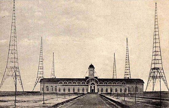
figure 13
An artificial ground/ earth plane of equivalent area, consisting of copper wires, was buried in the ground between the pylons. The end of the aerial wires was terminated as one twisted strand, enveloped in a copper tube, and entered the tower of the main building through an insulated sleeve (figure 15) . Inside, the strand was connected to the aerial coil via the wavelength selector switch (figure 16).
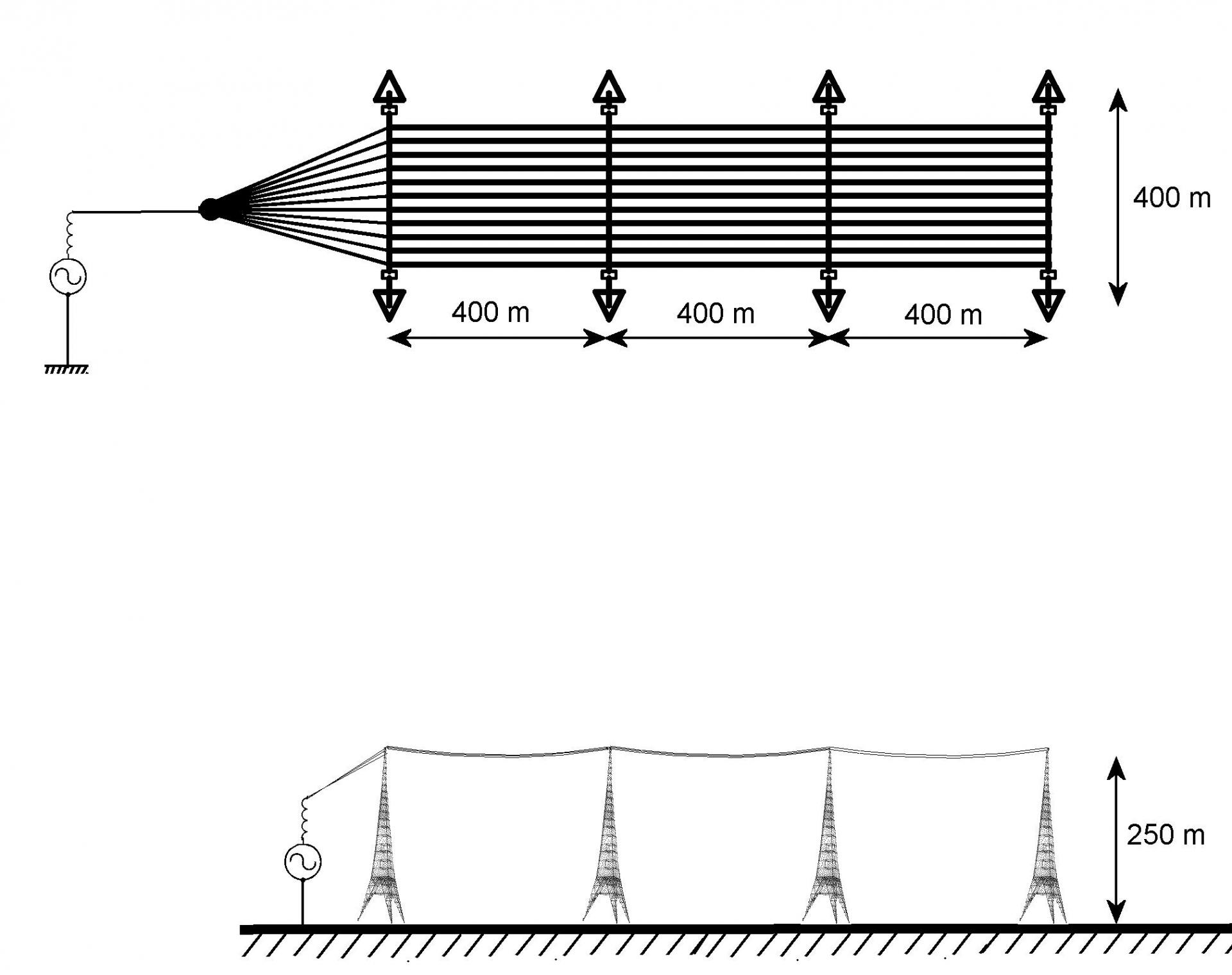
figure 14 - Drawing of the aerial system
The aerial system and the artificial ground/ earth plane formed the plates of a gigantic capacitor which, together with the aerial coil, formed a tuned circuit producing a large high frequency current which, by passing through the aerial, resulted in energy being radiated in the form of electromagnetic waves. The aerial coil, made of 100mm diameter cable, was 6m high and 6m in diameter, with intermediate connections selected by a switch (figures 18 & 19). As a result, it was possible to transmit on seven different wavelengths between 19150m (15666 Hz) and 23450m (12793 Hz).
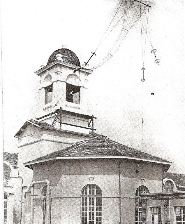
figure 15 - The antenna tower
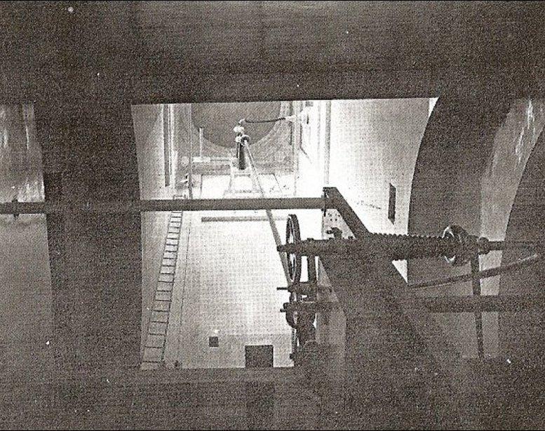
Figure 16 - Inside the tower, the strand was connected to the aerial coil via the wavelength selector switch.
The 560-tonne pylons, each assembled with 24000 rivets, were tripods consisting of a triangular 190m pyramid mounted on top of three inverted 60m pyramids. The sides of the triangle formed by the bases measured 66m (figure 17). The pylons could withstand a force of 10 tonnes at the top, where there was a 3m2 platform (accessed by ladder).
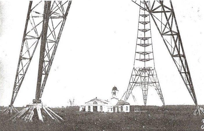
figure 17 - The 560-tonne tripod pylons.
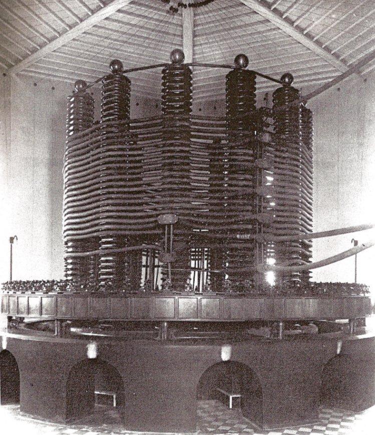
figure 18 - The antenna coil
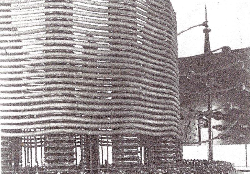
figure 19 - The antenna coil, at right side details of switching
5) The arc transmitter (1920-1923):
The station was equipped with two identical arc transmitters, one of which was kept on standby.
? Working principles : The intensity of an electric arc is varied periodically in order to produce a continuous oscillation at the desired frequency (see the appendix 1 at the end).
To achieve this the arc is controlled by a magnetic ‘blow’ system based on the Laplace-Lorentz effect. A very intense magnetic field applied perpendicular to the axis of the electrodes causes the arc to bend towards the point of breaking. As soon as the magnetic field disappears the arc reignites automatically due to the highly ionized atmosphere. The frequency of the arc current is proportional to the intensity of the magnetic field: the greater the field, the faster the arc breaks (figures 20 & 21). The arc consumed 800 amps at 1250 volts with a conversion efficiency in the order of 50%. External ponds held water for cooling, essential for dissipating the 500kW of energy lost through heat in the transmitter.
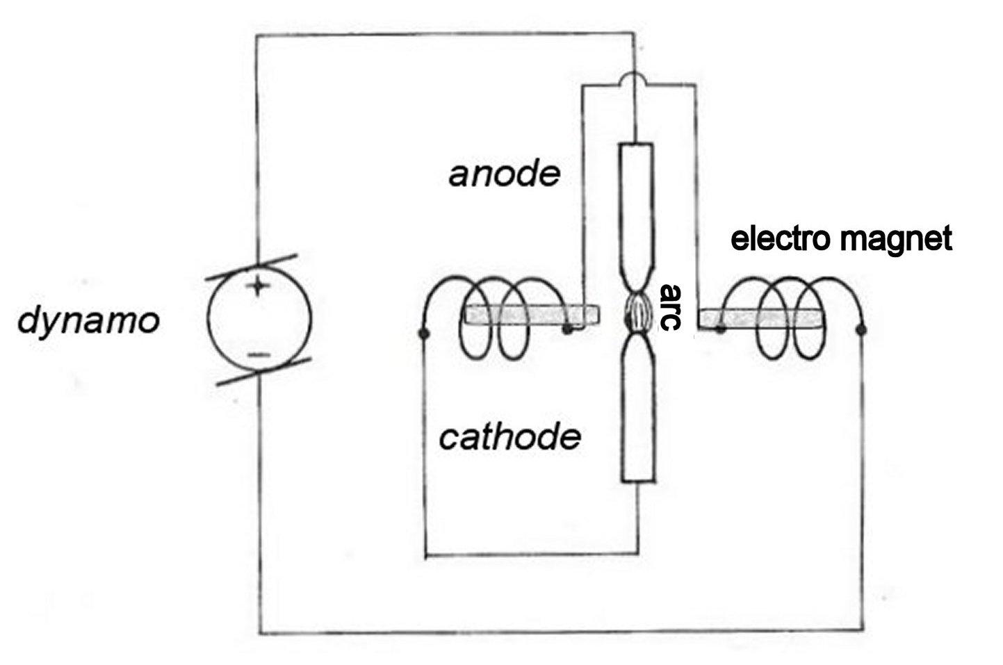
figure 20 - The blown arc
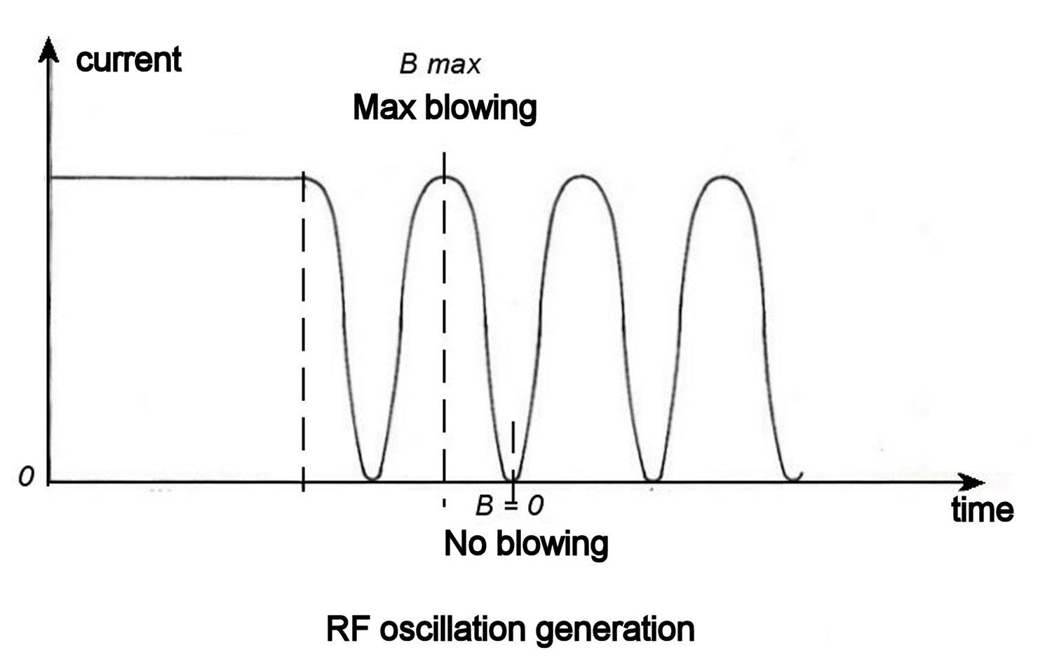
figure 21 - RF generation
? The arc chamber and electromagnet : Figures 22 & 23 illustrate the complete setup, which weighed about 80 tonnes (the magnetic circuit alone weighed 70 tonnes and could generate a field of 17000 gauss). The coils of the magnetic circuit were oil-cooled. For it to work, the primary winding was connected in series with the arc, which also prevented feedback into the armature of the generator. An auxiliary winding was fitted to provide an adjustable field in opposition to the main field and was powered by a 30kW generator. The anode was made from 10mm copper tube and cooled by circulating water. The cathode was a 500mm long, 40mm diameter carbon rod, rotated slowly by a small electric motor in order to ensure even erosion and replaced every 24 hours. A mixture of alcohol and oil was sprayed into the arc chamber (20 litres per day) to improve the condition of the carbon rod surface and the efficiency of the arc. A door in the chamber gave access for cleaning purposes.
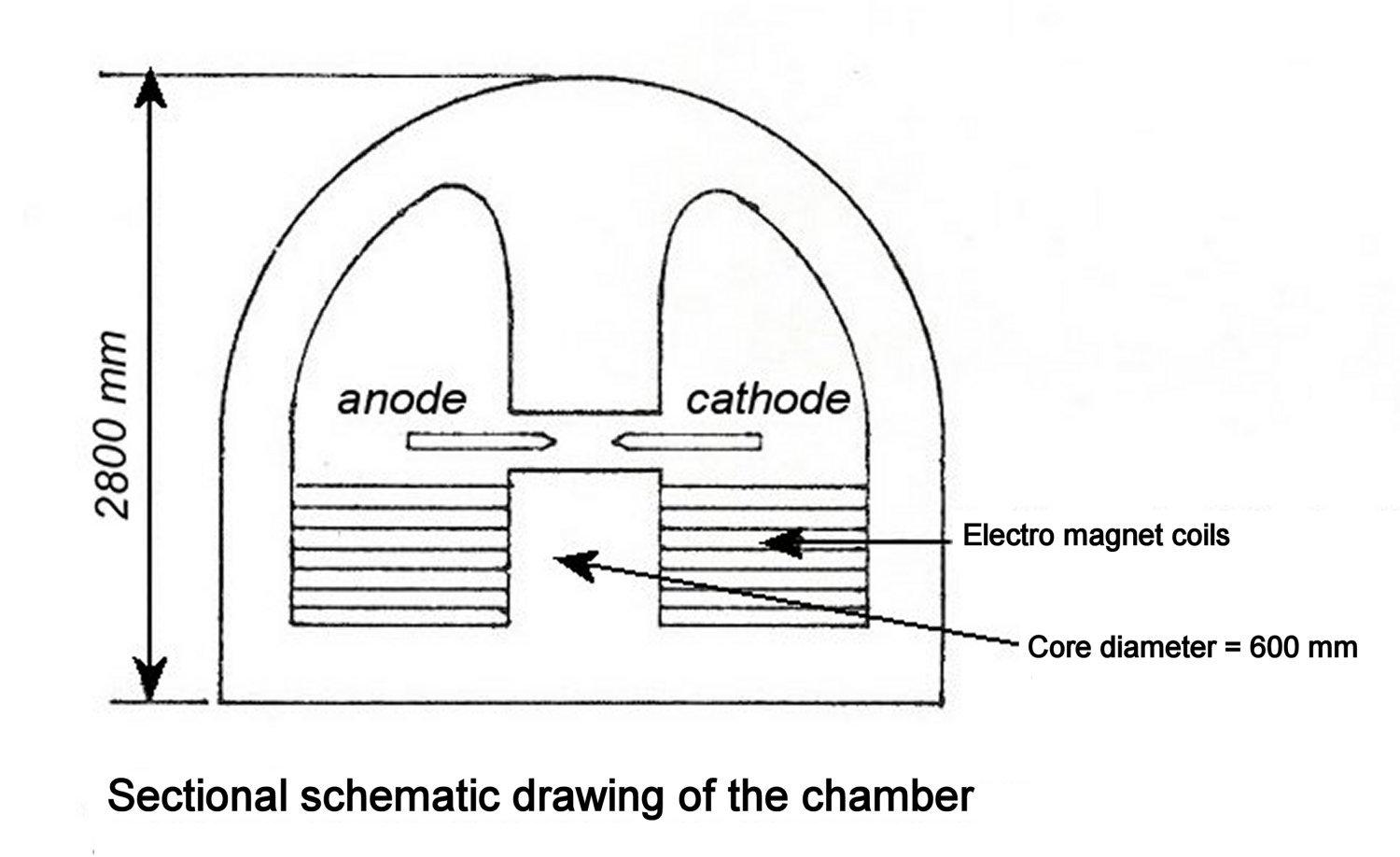
figure 22 - The transmitter chamber
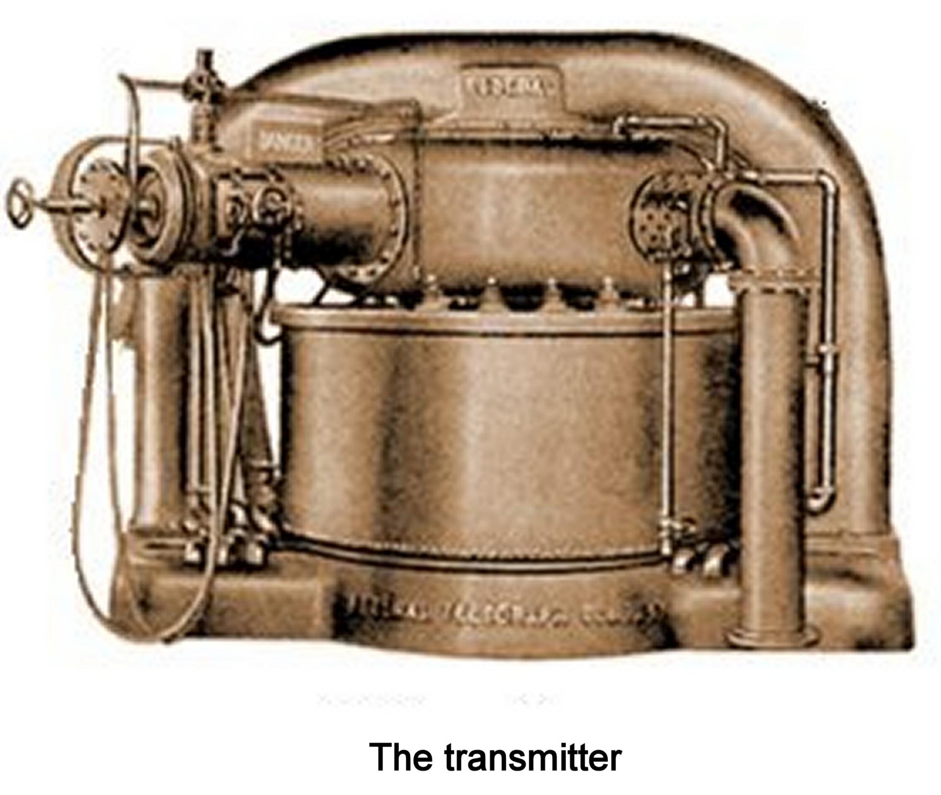
figure 23 - The transmitter
? Power Supply: Each transmitter was powered by a Gramme dynamo driven by a synchronous motor running on 2200 volts and capable of delivering 800 amps at 1250 volts.
? Frequency adjustment: The arc is placed between the aerial coil and the ground/ earth connection (figure 24). Adjustment of the auxiliary winding current enables the transmit frequency to be varied.
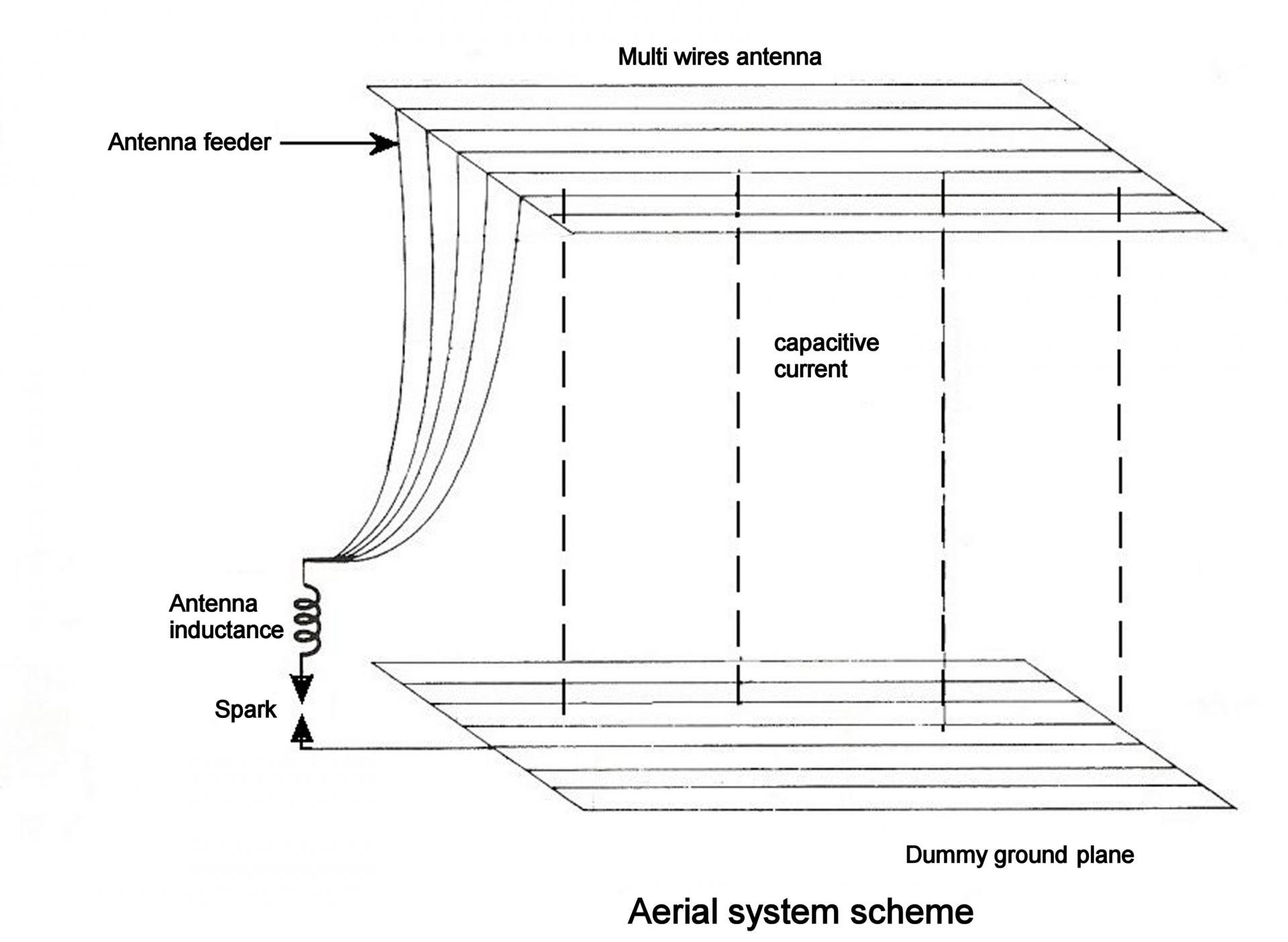
figure 24 - Frequency adjustment
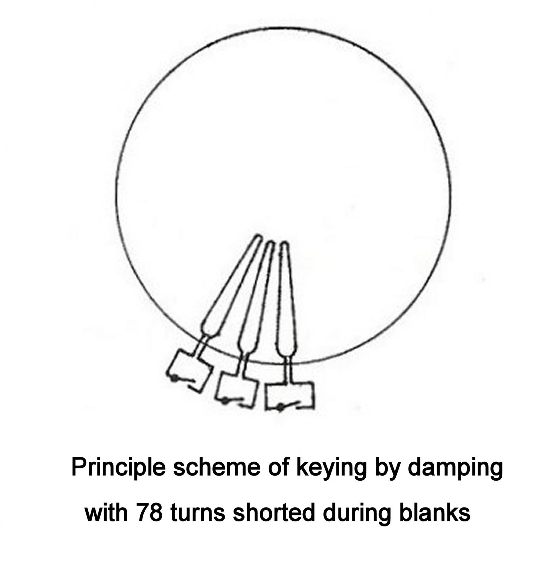
figure 25 - Keying principle
? Transmission of information In Morse: Morse normally works via on-off keying, the key being a simple switch: closed, current passes, the carrier wave is transmitted to give a dot or a dash; open, no current so no carrier wave for a space or a blank (or vice-versa). But the arc does not stabilise instantaneously so it is not possible to cut transmission at the rate of the key activation. Frequency-shift keying was therefore adopted, as described below. Sixty-Eight small coils are arranged at the base of aerial coil and coupled to it. When the key is open these coils are simultaneously short-circuited, which damps the oscillating circuit and changes the load, with the frequency shifting from F1 to F2 due to the resulting detuning (figure 25). The receive operator decodes the signals by beating with the receiver tuned to F1. However, with F2 being very close to F1, he had to discriminate by concentrating on the tone corresponding to F1. The arc transmitter produced a wide range of strong harmonics, which could seriously affect the reception of other stations. Therefore a different method of transmission would need to be found quickly.
6) Installation of a high-frequency alternator in 1923 (callsign : FLY):
A Bethenod-Latour alternator was installed in 1923. This could generate frequencies three times higher than a classic alternator. The air gap was only 1mm. The machine rotated in a rarified air atmosphere in order to decrease friction. The forged steel rotor, with very thin layers of silicon on its periphery, had no conductive windings (figure 26). The machine was driven by electric motors, one on either side of the shaft, and had a speed regulator which stabilised the frequency. Transmission frequency was now fixed at 15666 Hz (19150m). The eight coils of the alternator were coupled to the aerial coil by TESLA triple winding transformers (figure 28) which had flat-wound coils made of 50 x 2mm copper ribbon (figure 27). The operating principle was pretty basic : to break transmission the centre winding was shorted, thus behaving as a screen, which reduced the coupling between primary and secondary to virtually zero. The load on the alternator became very light and power consumption reduced. Figure 28 shows TESLA transformers with their associated switches. The arc transmitters were kept as backup.
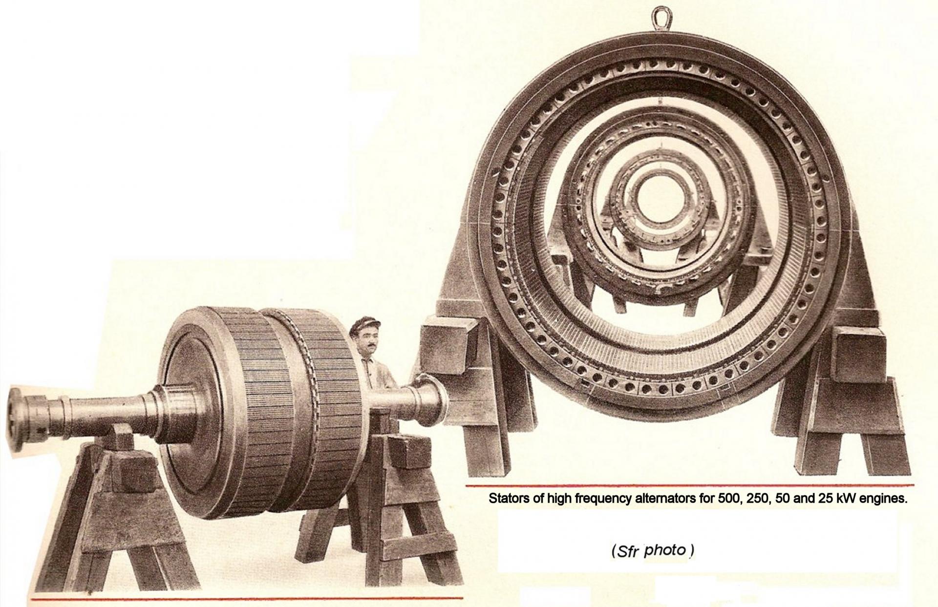
figure 26 - Stator and rotors of high frequency alternators
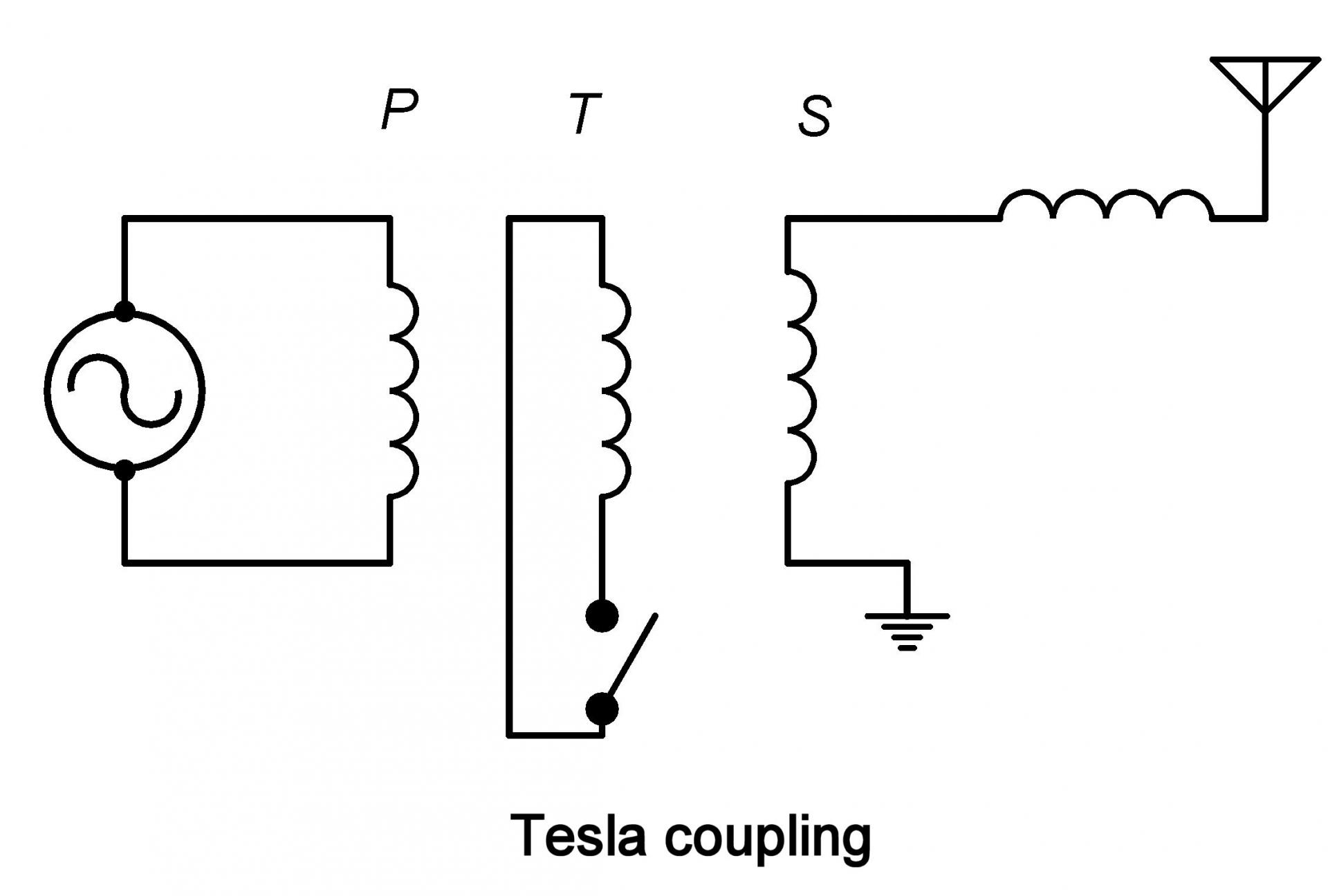
figure 27 - Tesla method of coupling
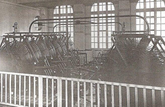
figure 28 - The Tesla transformers
This had huge advantages over the previous technique: more efficient, low power consumption during spaces/ blanks, easier to receive and less harmonics.
7) Installation of shortwave thermionic valve (vacuum tube) transmitters:
Later, shortwave transmitters were installed. The first one in 1937 with a power of 50kW on 6802kHz (callsign : FYM). The second in 1938 with 15kW on 17530kHz (callsign : FYM2).
(Source: History of The Bordeaux Station - La Fayette.)
Appendix 1: Principle of the arc transmitter.
Poulsen's arc transmitter, named after its inventor Valdemar Poulsen, a Danish researcher, was used in early radio to convert direct current into radioelectric energy. This device, which could generate frequencies of up to 200kHz, was patented in 1903. After a few years of development, the arc transmitter technology was transferred to Germany and Great Britain in 1906. Further development in Europe was very different from that in the United States. For several years Poulsen's technology had great difficulty in establishing in Europe, while in the United States a widespread radio telegraphy system quickly emerged. Later the U.S. Navy, in turn, would adopt the Poulsen system. Only the passive frequency-conversion arc transmitter was suitable for portable or marine use. Poulsen's arc transmitter was the dominant mobile radio system for about ten years, until the arrival of thermionic valves (vacuum tubes).
Imagine an electrical arc occurring between two electrodes. If a series capacitor and inductor are connected across it, we find that continuous oscillations are generated (figure 30). To transmit, the circuit is coupled to an aerial that enables the oscillation to be propagated in the form of radio waves. The device is simple and robust and has an efficiency of about 40%.
In its industrial realisation for the navy, the arc is ‘blown’ by an electromagnet. The cathode (-) is made of carbon, the anode (+) is copper and is cooled by circulating water; the arc burns in an atmosphere of alcohol vapour. The transmitter consists of a hydrogen-filled, water-cooled, bronze chamber in which the arc occurs between a carbon cathode and copper anode, also water cooled. On the top and bottom of this chamber are the coils that surround the two poles of the electromagnet's magnetic circuit. These poles project into the chamber, on either side of the arc, and generate a magnetic field (figure 31).
How it works:
Unlike the spark transmitter, Poulsen's arc transmitter generates a continuous wave, which is a considerable advantage because damped waves are less efficient and very rich in harmonics. Poulsen's arc is based on Duddell's discovery that if an electric arc is connected to a circuit that includes a capacitor (C) and inductor (L), it oscillates at a frequency determined by the values of L and C. This phenomenon is due to the fact that the relationship between the voltage at the arc terminals and the current passing through it exhibits a negative dynamic resistance, in other words when its current increases, the voltage at its terminals decreases.
Imagine an LC circuit connected to the terminals of an arc. At some point, the capacitor charges by drawing part of the current from the arc. The arc voltage increases, resulting in increased charge on the capacitor. Once fully charged, the capacitor draws no further current, the current in the arc increases again and its voltage decreases, leading to the capacitor discharging. By supplying energy the arc undamps the LC circuit, which then goes into a state of continuous oscillation. Duddell's system could only operate with a capacitors of at least 1uF, which limited the use of the arc at high frequencies.
Poulsen's great discovery was to have the arc operate in a hydrogen atmosphere which, by cooling the arc, increased the slope of the current-voltage characteristic; and also to greatly reduce the current by introducing a very strong transverse magnetic field to ‘blow’ the arc, thus obtaining a higher voltage. This enabled use of lower value capacitors, and therefore higher operating frequencies.
Note that the Lafayette transmitter was a slightly different variant of the original transmitter in that the relaxation oscillation is created totally by the action of the electromagnet. Since the arc takes some time to strike and stabilise, the transmitter cannot be simply on-off keyed for telegraphy (morse). Frequency shift keying is used, as outlined previously. In this case, the arc is permanently ignited and part of the LC circuit (one or two turns) will be short-circuited when the key is closed (or vice versa, as in the case of Lafayette). Thus transmission will be on one of two different frequencies depending on whether the key is closed or not. If these frequencies are sufficiently different (in the order of 5%), and the receiving station sufficiently selective, the operator will be able to hear conventional telegraphy when set to the frequency corresponding to the key in the closed position. The system was very effective on frequencies ranging from a few kilohertz to a few dozen kilohertz.
(Source: The Poulsen System from Wireless Telegraphy by W.H. Marchant (1914))
Appendix 2: High-frequency alternators.
The engineers who developed these machines at the ‘Societe Francaise Radioelectrique’ (SFR) were Joseph Bethenod and Marius Latour. The mechanical design required to obtain high frequencies directly posed considerable challenges. This led to the use of exceptionally high rotational speeds, very small polar steps and extremely narrow air gaps. These high velocities increased friction losses, distortion, and dangerous vibrations. In addition, such small air gaps called for extreme precision. The combined efforts of SFR and ‘la Societe Alsacienne de Constructions Mecanique’ of Belfort solved these problems with unparalleled success.
The first, 5kW, machine was commissioned in 1915 at the Lyon La Doua station and a second, 125kW, machine was installed there in 1918. Operation and reliability proved impeccable, the signal was free of harmonics and very stable. This type of alternator has been built for various powers, from 25kW to 500kW, and for wavelengths of 8000 to 20000m. The rotational speeds (from 2500rpm for the 500kW alternator to 6000 rpm for the 25kW alternator) was maintained constant by a very fast-acting controller, regardless of the load variations. Rotating in a rarefied atmosphere to avoid friction losses and force-cooled by circulation of oil under pressure, the alternator offered a very high efficiency (84% for the 500kW machine, see SFR photo above).
These alternators could be coupled together on the same aerial in order to increase the power, depending on the needs of traffic or propagation, or even for multiplex operation, (transmitting simultaneously on different frequencies on the same aerial), whilst avoiding interaction between alternators.
--------------------------
I want to thank my friend Neil for the translation, a great work for which he spent a lot of his time, thanks again Neil !
Daniel
References:
? ‘25 années de TSF’ : Société Francaise Radioélectrique (SFR) : 1935
? Book published by : la Direction des Télécommunications du Réseau International : ‘Histoire de Bordeaux La Fayette’ : by M. Nicolazzy : 25 April, 1975.
? Book on : le Bassin d’Arcachon durant 1914/ 1918 : Patrick Boyer co-author.
Existing documents:
a) Gaumont-Pathé news archives : short film, on 16 mm film, showing the inauguration of the station.
b) Brochure ‘Bordeaux-La Fayette’ : edited by l’Association pour l’Histoire de la Poste et des Télécommunications en Aquitaine.
Copyright TLR 2018 - Toute reproduction interdite sans autorisation.
Date de dernière mise à jour : 04/06/2024
Commentaires
-
 http://aheiden.net/Elmer_Peterson_WWI_photos/tower1.jpg
Hello I noticed one of the photos in the article was taken by my grandfather in 1918.
There are more at the site shown above.
regards,
Al Heiden Thanks for your interest
Regards
Ajouter un commentaire